Lab 4
Quick Stats
Time Spent: 16 Hours, 11 minutes and 51 seconds
Timers Initialized: 2
Failed Imperial Marches: 1
Blown LM386 Amplifiers: 0.5
How Helpful the Oscilloscope Was: Very
Debugger: Thoroughly Stepped
E85 Lab-goers Annoyed: 4
E85 Lab-goers Impressed: 0
E155 Classmates Impressed: 1
Overall: Success
See my Blog Reflection for more!
Lab 4: Digital Audio
Lab Task: Intro to MCU and Writing Effective Headers
Lab 4 tasks students with creating a digital audio system capable of playing a simple tone-based song. Enabled by the MCU for the first time, rather than the FPGA, this lab has an added challenge. Typically, a STM32 programmer would use CMSIS, a standardized framework built for helping users implement MCU functions easily and consistently. Instead, in our lab 4 case, students are tasked with building out their own header files to enable such control. This practice aims to develop the skills needed to parse and implement the 1600 page reference manual, hopefully making future projects easier to understand and implement with or without the aid of tools like CMSIS.
Note: I need to thank and credit Professor Joshua Brake for providing the Lab 4 starter code here, which lists the C array which encodes the frequencies and delays for Für Elise, and the RCC Configuration tutorial here. The latter tutorial was partially completed during a lecture day, and includes the unmodified .c and .h FLASH files which ensure that code can still be downloaded. It also contains the GPIO files, which I modified to include both port A and port B, and the RCC tutorial itself, which gives a framework for students to enable the PLL.
The Hardware
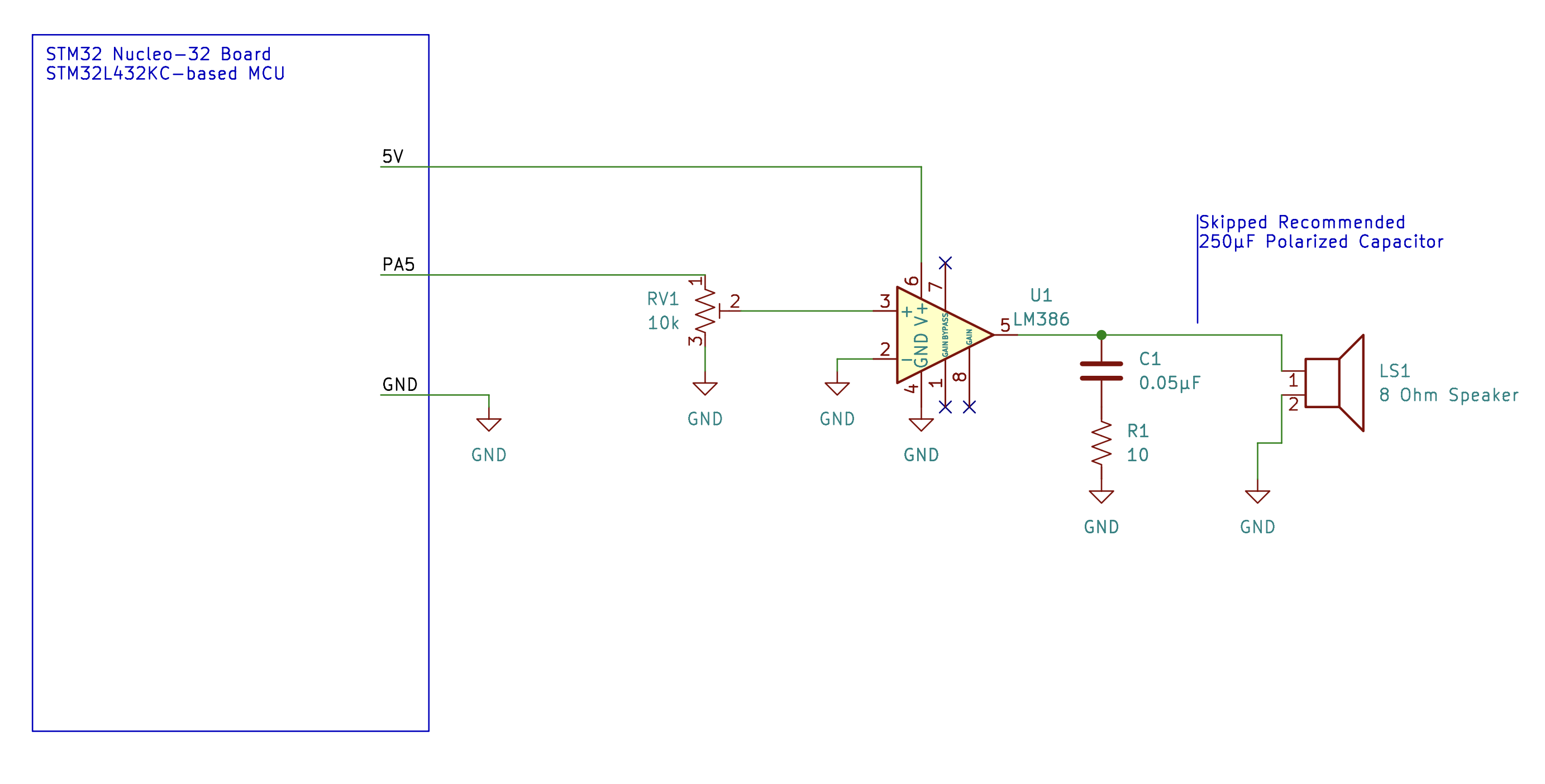
The circuit for this lab was simple – connect an 8 Ohm speaker to the MCU through an audio amplifier stage. We selected the LM386, a common low-power IC often used for audio applications. We were able to hook up this circuit directly as shown by the example application circuit in the data sheet. Our resulting circuit may be seen in Figure 1 below. Note that I ended up removing the final capacitor that ran in series with the speaker, as it seemed to be cutting off the upper end of my frequency spectrum. Everything sounded extra low and down-shifted.
Steps to Enable Sound Output
I knew that my ultimate goal was to build a PWM generator capable of producing a desired frequency. Changing this frequency would allow me to produce any tone, or note, I wanted. I also needed a way to precisely control when this PWM triggered and changed frequency. Changing this delay would allow me to control the cadence of the music. Luckily, both of these can be accomplished with the same fundamental unit in an MCU – timers! With this in mind, I created the following task list of big picture action items:
- Establish a known system clock.
- Enable clock output to peripheral timers
- Set a timer for controlled delay
- Set a timer for PWM
- Enable output pin for PWM alternate functionality
Note: For the most thorough description of which Registers to use and Bits to change, see my code, found in my github here.
Steps 1 and 2 – Clock Control
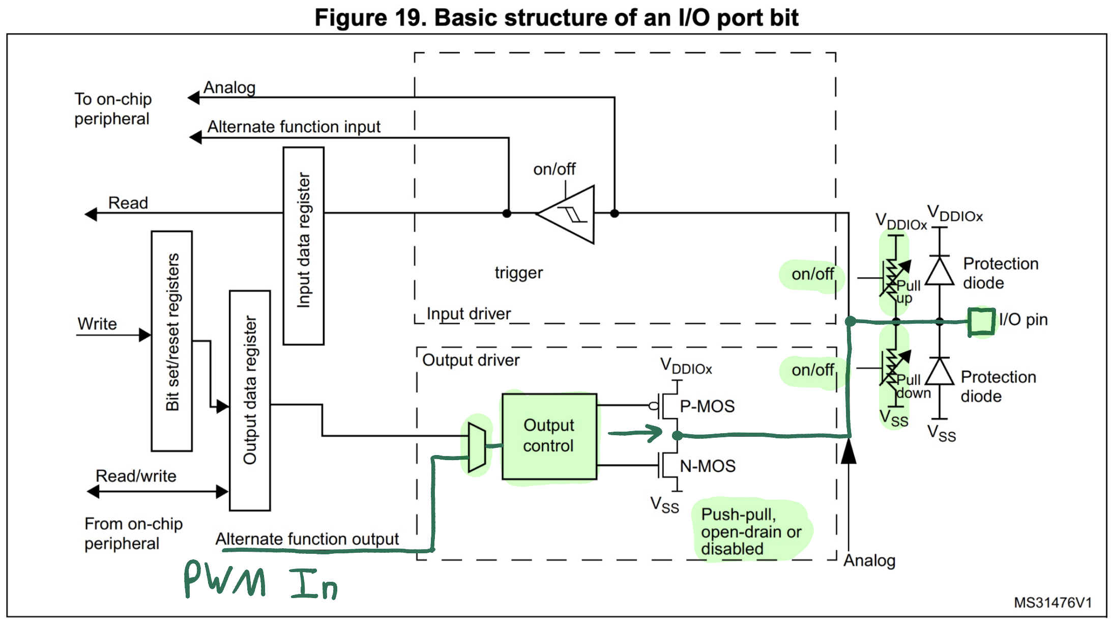
My block diagram for this lab presents itself in a less obvious form, but it more clearly outlines the steps that I must go through in order to accomplish the steps above. Starting with Figure 13 (Clock Tree, from page 180 of the reference manual) as a base, I developed the quasi - block diagram in Figure 2 to describe how I would accomplish steps 1 and 2 above. I chose to enable the PLL, using the MSI as a source, as highlighted in Blue. I then set the system clock source to PLL, as shown in Purple. Finally, I could feed these clock signals to the peripheral timers, as shown in Red.

Note that I did not leave my choice of where to run the Red timer connections up to chance. I chose timers 2 and 6 to generate my frequency and delay because they had the requisite functionality and could be enabled by the same clock signal. I chose timer 6, one of the most basic timers available on our MCU, as a delay timer. I felt that it would serve as a low-stakes introduction to using timers, helping me build up the skills for enabling the PWM on a separate timer. After all, its only function in my system is to count up a precise delay – a basic function indeed. I chose timer 2 to generate my frequency output because it’s a general purpose timer with a PWM function built in.
Finally, I want to note the x1 or x2 block along the red line, right before the signal feeds out to the timers. Originally, I did not know how to set this. I have since come to learn that this value is set to x1 automatically if both bus prescalers are equal to 1, and the value is set to x2 in any other case. Since I chose to divide by 2 with both the AHB and APB1 scalers, this block was set to x2. This gave me a final SYS_CLK = 10 MHz, and a TIMER_CLK = 5 MHz.
Steps 3 and 4 – Timer Control
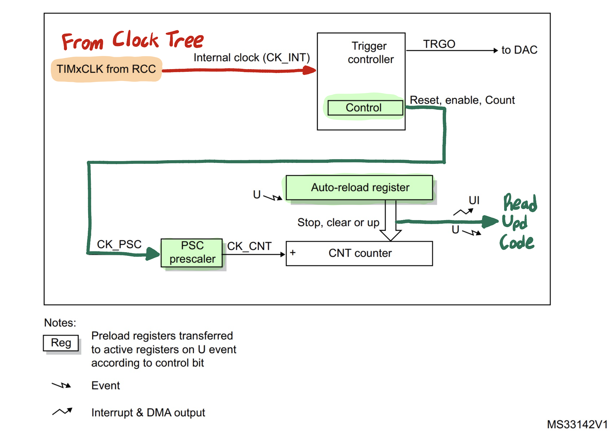
To describe the steps required to enable Timer 2, I used Figure 325 in the STM32 reference manual as a base. Tracing the required signal path to generate a delay, I produced the quasi - block diagram shown in Figure 3 below. This one was relatively straightforward. The key steps to remember are enabling the control unit after setting the desired prescale and auto-reload values.
To understand more about how the timer works, I used Figure 328 in the STM32 reference manual, shown in Figure 4 below. I thought about the timer like this: once enabled, the timer counts up. It stores its current count value in the Counter Register. This counting occurs at a rate determined by the counter clock, which is equal to the Internal Clock divided by the Clock Prescaler. The Counter Register continues counting up until it is equal to the Auto Reload Register (not pictured, but can be set by the user).
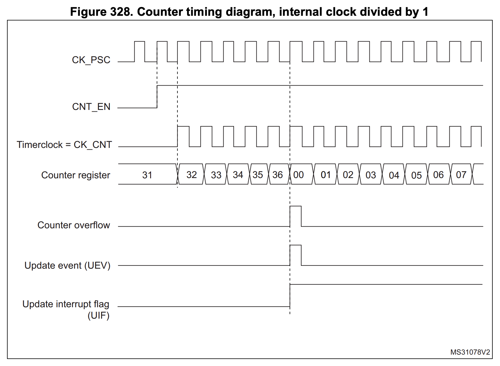
We set the system clock speed such that it is 5 MHz by the time it reaches the timers. We know and can control the prescaler – I set it to 1, essentially meaning that this 5 MHz system clock passes straight through to the counter. So, the counter counts up at a frequency of 5 MHz. In other words, it will count up to 5 million in a full second. That would be useful if I wanted to count seconds, or if the counter register was big enough to store that big a number. However, neither of these are true. So, that’s why we control the Auto Reload Register – it tells the counter when to restart from 0. By carefully choosing the value we put in the Auto Reload Register, we can tell the timer to count up in millisecond increments, microsecond increments, or anything between. For example, if we set it to 1,000, then the counter would count a total of 5 thousand times, instead of 5 million.
I set my timer so that a single cycle of counting takes 1 millisecond. How does one use this to create a useful delay function? In order to interface the software with the counting hardware, we first need to understand what the software can see. When the timer reaches its maximum, it creates an update event. Listed in the diagram below as (UEV), this is how the hardware signals itself to reset from 0 and continue counting. Once the counting starts again, the hardware automatically resets the UEV bit. So, a user who wanted to use this timer to count up to 10 milliseconds could wait for 10 of these events to generate. However, this requires a strict timing – so, we have a better solution. The UEV bit also sets the UIF bit – Update Interrupt Flag. This flag turns on every time the counter reaches its maximum, and stays on until turned off by software. Turning it on or off does not affect the counting itself. So, by instead tracking this UIF bit, we can make sure that we don’t miss a counting cycle.
With this understanding, generating a PWM signal is rather straightforward. Timer 2 has a built in compare function, which outputs 0 if counter is less than the compare number and 1 if the counter is greater than the compare number. If you set the compare number to be half of the Auto Reload Register, then the timer will output a square wave, going from 0 to 1 midway through a single timer cycle. So, you can generate a desired PWM wave by storing select values in the Auto Reload Register (the top value), the Capture/Compare Register (the middle value), and the Prescaler Register (which sets the counter frequency, like TIM6).
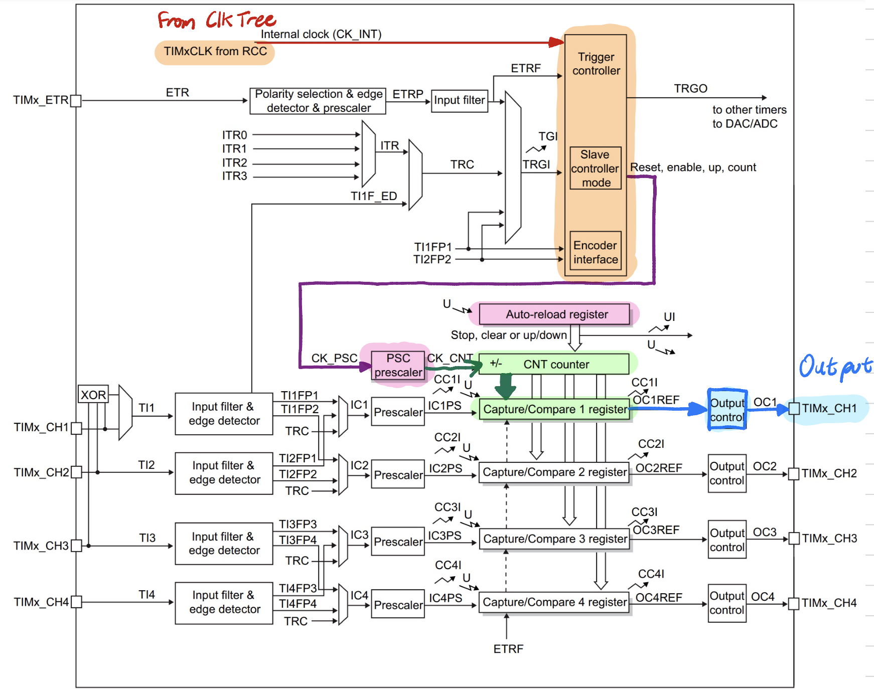
However, although the idea behind generating a PWM is rather simple, timer 2 is far more complex and requires special attention in its block diagram. Specifically, there are 4 channels, and additional stages of control (ex. output control, capture/compare control). If any of these values is incorrectly set, say for the wrong channel to to the wrong value, the entire chain breaks down. Figure 5 above shows the block diagram path of the signal, highlighting the values that must be updated. In addition, the reference manual contains a section describing which values need to be set to enable PWM output.
Step 5 – Output Pin Control
Great! We have a way to control a precise delay, and can generate a PWM wave. Except right now, that wave signal is stuck on an internal timer – we need to get it out to a pin so we can interface it with the world. So, we need to follow another path through to an output pin. Most of these pins have alternate functions, allowing them to be connected to some internal system like our timer 2. To understand this signal path, we may look to the quasi - block diagram in Figure 6 below. For understanding more about the software control and interconnects between systems, the table describing these internal connections may be found in the STM32 data sheet (page 55, Table 15).
Supporting Calculations
This section contains the supporting calculations to show the analytical limits of my system’s delay and frequency generation, as well as the analytical and practical calculations which show the accuracy of my PWM frequency and delay timing.
Delay Limits Calculations
I designed my delay system to run on Timer 6, the basic timer, set to generate an Update and set the UIF every millisecond (<1% error from MSI and SYS_CLK). Given the design of this timer, it is not possible for my system to count delays under 1 millisecond. Thus, by design my minimum delay is 1 millisecond, with a minimum increment of 1 counting up.
On the other hand, my maximum delay is far higher. This timer can run for as long as the MCU is receiving power, which I will assume to be infinitely long (barring the heat death of the universe… or a power outage). However, the MCU needs to knock down the UIF every time it wants to perform a delay. My delay function can only do this for as long as the for loop can continue counting up. Since the for loop counts until it reaches the variable uint32_t milliseconds, then the maximum value of milliseconds is the maximum amount of times that my for loop can be executed. We know that a 32 bit number of all binary 1s, more easily expressed as 0xFFFF FFFF, is equal to 4,294,967,295 milliseconds. Converting to a more human-friendly number, we may say that our maximum delay is about equal to 49.7 days.
Frequency Limits Calculations
The limits of my delay function are relatively simple – the limits of my frequency function are less so.
The minimum frequency corresponds to the longest that the timer could count up to its Auto Reload Register. I load the register according to the following quotient function: ARR = TIMER_CLK/freq. Freq can only be an integer value, and we cannot divide by 0 (at the very least, it is undefined by C, even if it may by defined in SEGGER or CMSIS). So, it follows that we can set ARR highest by setting freq to 1. However, as I originally created the function, I did not realize that the 1x or 2x block was automatically set to 2x in my system. I was expecting a TIMER_CLK of 2.5 MHz, not 5 MHz. I noticed this error in testing, and although I initially couldn’t pinpoint the reason, I could fix it using my C function. To account for this 2x error, I passed the desired frequency into the function using a variable givenFreq. The passed variable relates to my actual freq variable as follows: freq = givenFreq/2. In effect, this doubles ARR, fixing the system. However, this fix means that the lowest frequency that I can actually pass into the function is givenFreq = 2, since this must be divided down to freq = 1. This quotient division on givenFreq thus sets my limiting factor. So, for my PWM frequency function, the minimum frequency that I can support is 2 Hz.
The maximum frequency corresponds to the shortest that I could set the ARR. In this case, that would be at a value of 1, where givenFreq = 10,000,000, setting freq = 5,000,000, finally making ARR = 1. If the ARR is set to its natural extreme of 0, the counter stops counting. That is to say, we cannot set ARR lower than 1 and still have an output PWM, so this defines our highest frequency. with TIMER_CLK = 5 MHz, ARR = 1 essentially means that the PWM flips each clock cycle. So, the maximum frequency that I can support is 2.5 MHz.
PWM Frequency Accuracy
There are two types of supporting calculations that I can provide to back up the accuracy of my frequency PWM generation. Firstly, analytically, we know that TIM2 runs off an internal frequency of 5 MHz. There is some error introduced when I set the Auto Reload Register, since I make use of the quotient function in C, not a true divisor which would account for the remainder. The worst possible remainder on the range of [220-1000]Hz would be a leftover 999. This would equate to a percent error of 999 / 5 MHz, or less than 0.025% introduced error. So, analytically, I expect my PWM wave to be within the given spec of <1% error. Additionally, the MSI internal clock which I use to generate my SYS_CLK is posted as having an error of <1%. So, again, I expect my PWM wave to fall within spec.
However, theory is not practice! Yet, I proved that my frequency is accurate there too, using an oscilloscope. For the set frequencies of 330Hz and 500 Hz, I generated the two oscilloscope plots below.
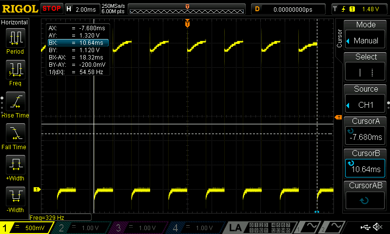
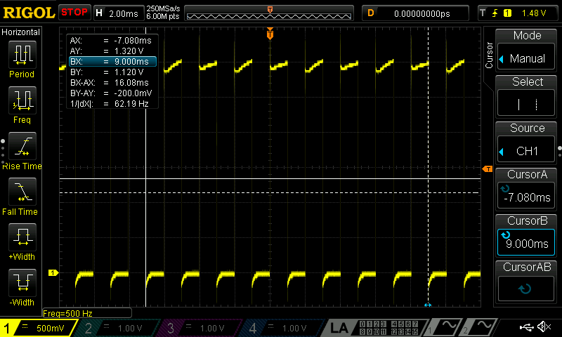
By using the total elapsed time between x number of cycles, I was able to deduce the period of each wave. For the 330 and 500 Hz waves, each had a period of 3.05 and 2.01 milliseconds respectively. This corresponds to a frequency of 327.5 Hz and 497.5 Hz, indicating that my PWM is running the slightest bit slow. However, given respective errors of 0.75% and 0.5%, both tests demonstrate that my error in frequency generation is <1%.
Delay Accuracy
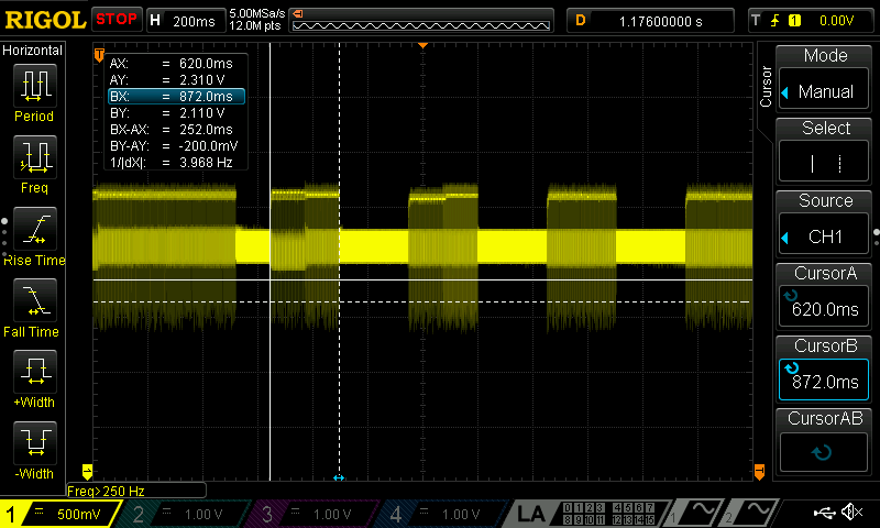
I can also support my timer delay, albeit with a caveat. The delay timer that I build was constructed to have a delay of 1 milliseconds. In reality, however, it had a delay of closer to 0.6 milliseconds. I was unable to deduce why this is the case. In Figure 2, there is a 1x or 2x multiplier which I was unable to find the register to control. I wonder if this multiplier was set to 2x, meaning that my analytical timer would count 0.5 milliseconds instead of 1. If there was then some significant unaccounted for lag, either in the system startup, turn off, or with some counter reset, then this could easily turn 0.5 into 0.6 milliseconds. However, this delay was consistent. It was easier to instead scale my Auto Reload Register by the appropriate amount than it was to hunt for the source of this error. After changing it by approximately 1 / 0.6 = 67%, I was able to show with my oscilloscope that each 125 millisecond note played for 126 milliseconds – within a <1% error spec, and within the error range of my MSI clock itself.
Conclusion
And that’s that! I created a working system which, as the System Demo shows at the top, is capable of playing Für Elise and the Imperial March. Check out my Github code here for a more in depth view of the MCU code itself – I put my best effort into thoroughly commenting each function and header definition.